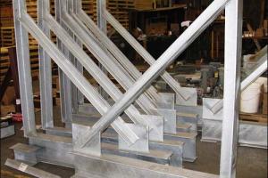
Analysis & Design Report for Store & Generator Room


It is a frame structure single storey unit & includes areas for various purposes, such as transformer generator space. Ultimate Strength Design (USD) or Load and Resistance Factors Design (LRFD) method is used for structural design of all the components. The concrete used for all structural members should have a minimum 28 days cylinder crushing strength of 3,000 Psi.
Introduction to the Project
It is a frame structure single storey unit & includes areas for various purposes, such as transformer , generator space etc.
Design Specifications & Design Methods
ACI (American Concrete Institute) is the governing code for design of the structure.
Design Methods
Ultimate Strength Design (USD) or Load and Resistance Factors Design (LRFD) method is used for structural design of all the components. USD method is based on load and resistance factors, which make it economical and deterministic as compared to the Allowable Stress Design (ASD) method. Sizes of the footings are designed using the allowable bearing capacity with an appropriate factor of safety (FOS).
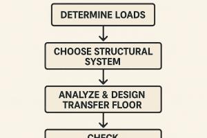
Loads on the Structures
The structures are subjected to some or all of the following load types:
- Self weight of the structure
- Dead Load of the floor finishing, walls etc.
- Floor live loads
- Earthquake loads
Design Criterion & Parameters
Parameters used in analysis and design are:
Load Factors and Load Combination
The structures are investigated for the following load combinations with appropriate load factors for different types of loads.
- Service Load Combination U = 1.0 D + 1.0 L
- Ultimate Load Combination U = 1.2 D + 1.6 L
- Earthquake Load Combination U = 0.75 x (1.2 D + 1.6 L + 1.87 E) And U = 0.9 D ± 1.43 E
- Earth pressure Load Combination U = 1.2 D + 1.6 L + 1.5 H And U = 0.9 D ± 1.7 H
Where,
D = Dead loads including self-weight of the structure, Weight of floor finishing, walls and backfill soil.
L = Floor Live Loads
E = Earthquake loads
H = Horizontal earth pressures
Resistance Factors
- Flexure and tension in reinforced concrete, = 0.90
- Shear and torsion in normal density concrete,= 0.85
- Axial compression with spirals, = 0.75
- Axial compression with spirals, = 0.70
- Bearing on concrete, = 0.70
Material Properties
The concrete used for all structural members should have a minimum 28 days cylinder crushing strength of 3,000 Psi. The reinforcement steel used in the structural members should be deformed bars having minimum yield strength of 40,000 Psi conforming to ASTM standards A615.
Structural Analysis Method/Software used
For structural analysis & designing, three-dimensional analysis software ETABS & SAFE were used & cross checked using ACI design Guidelines. These softwares are based on the Finite Element Method of Structural Analysis.
Elements used in Three Dimensional Structural Models:
- Shell elements with the capabilities of resisting plate bending and membrane force (in plane actions) are used for modeling of slabs and concrete wall panels
- Thick Plate Shell Elements are used for modeling of the elements where through-thickness shear deformations are important/possible, like pile caps and footings.
- Frame elements are used for modeling girders/beams, columns, etc.
Procedure Adopted for Calculation of Earthquake Loads
Equivalent static lateral force procedure of UBC is adopted for the project. Based on the Seismic Zoning map of Pakistan, Peshawar & related areas fall in the minor seismic zone (zone 2b)
The lateral force procedure of UBC is given below:
Design Base Shear (1630.2.1)

Where,
R= Response modification factor
I= Occupancy importance factor
T= Fundamental period of the structure
W= Total service dead load plus applicable portion of live load
Cv= Earthquake coefficient depending on seismic zone
The total design base shear, need not to exceed:
V = 2.5 Ca x l x W / R
The total design base shear shall not be less than:
V = 0.11 Ca x l x w
T = Ca (hn)3/4
Alternatively T= 0.1 N (For moment resisting frames with no. of stories less than 12)
where, N= number of stories
Vertical Distribution of Forces:
V = F + Σ (F)
Ft = 0.07 T V
Ft = (V - Ft) wshs / Σ w x h
Ft need not exceed 0.25 V and may be considered as zero where T is 0.7 Seconds or less. The remaining portion of the base shear shall be distributed over the height of the structure, including level, n, according to the above mentioned formulae:
The data for finding base shear is:
S.No Seismic Load Factors Values:
(Based on seismic zoning)
- Z = 0.2
- Cv = 0.4
- Ca = 0.28
- I = 1
- Ct = 0.03
- R = 5.5
Design Equations for Concrete Structure
Following design equations of the Ultimate Strength Design method are adopted for various structural components:
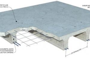
Slabs and Foundation
Design equations for flexural design of the slabs are:
Mu = As fy (d-a/2)
a = As fy / 0.85 x fc' x b
Beams
Design equations for flexural design of beams and stiffeners are:
Mu = As fy (d-a/2)
a = Asfy /0.85 x fc' x b
In case of doubly reinforced beams, T-beams and L-Beams these equations are modified accordingly.
Design equations for shear design of normal beams are:


Design equations for shear design of deep beams are:

Columns
Two methods are generally used for design of the bi-axially loaded columns i.e. the Load Contour Method and Reciprocal Load Method. Also the Concrete Design Module of SAP2000 automatically accounts for slenderness ratios of the connecting elements, lateral bracing (sway conditions), and relative stiffness of the columns.
Design Summary
Loads Calculation for building
Live Load on slabs of Ground floor (not used for single storey building) 60 PSF
Live Load on roof 40 PSF
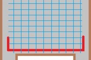
Design of SLAB
Type of slab = two way slab
Total depth of the slab = 5 in.
Preliminary effective depth of the slab = 4 in.
Maximum bending moment in short direction = 21 k-in
Maximum bending moment in long direction = 17 k-in
Steel reinforcement in short direction = # 4 @ 8" c/c (As = 0.29 in2 )
Steel reinforcement in long direction = # 4 @ 8" c/c
Minimum allowed required steel reinforcement area/unit width = 0.002 x b x d = 0.002 x 12 x 4 = 0.096 in2.
Max. Allowed Steel Reinforcement / unit width for the slab section =0.0206 x b x d= 0.0206 x 12 x 4 = .98 in2
This reinforcement steel is sufficient against the applied bending moments. This reinforcement steel is not less than the minimum requirements nor greater than the maximum allowable.
Summary of Design for Beams:
Design of Beam 1
Total depth of the beam, = 17 in.
Preliminary effective depth of the beam = 14.5 in.
Web width of the beam = 12 in.
Minimum required steel reinforcement = 0.005 x b x d = 0.005 x 12 x 14.5 = 0.87 in2.
Max. Allowed Steel Reinforcement for the Rectangular beam section =0.0206 x b x d= 0.0206 x 12 x 14.5 = 3.58 in2.
Main Steel provided = 3 # 5 bars
Shear Reinforcement Steel = #3 bars @ 7 in c/c at ends & centre of the beam.
This reinforcement steel is sufficient against the applied bending moments. This reinforcement steel is not less than the minimum requirements nor greater than the maximum allowable.
Design of Beam 2
Total depth of the beam, = 17 in.
Preliminary effective depth of the beam = 14.5 in.
Web width of the beam = 12 in.
Minimum required steel reinforcement = 0.005 x b x d = 0.005 x 12 x 14.5 = 0.87 in2.
Max. Allowed Steel Reinforcement for the Rectangular beam section =0.0206 x b x d= 0.0206 x 12 x 14.5 = 3.58 in2.
Main Steel provided = 3 # 5 bars
Shear Reinforcement Steel = #3 bars @ 7 in c/c at ends & centre of the beam.
This reinforcement steel is sufficient against the applied bending moments. This reinforcement steel is not less than the minimum requirements nor greater than the maximum allowable.
Design of Beam 3
Total depth of the beam, = 17 in.
Preliminary effective depth of the beam = 14.5 in.
Web width of the beam = 12 in.
Minimum required steel reinforcement = 0.005 x b x d = 0.005 x 12 x 14.5 = 0.87 in2.
Max. Allowed Steel Reinforcement for the Rectangular beam section =0.0206 x b x d= 0.0206 x 12 x 14.5 = 3.58 in2.
Main Steel provided = 5 # 5 bars
Shear Reinforcement Steel = #3 bars @ 7 in c/c at ends & centre of the beam.
This reinforcement steel is sufficient against the applied bending moments. This reinforcement steel is not less than the minimum requirements nor greater than the maximum allowable.
Design of column C1 & F1
Size of column = 12" x 12"
Max. Reinforcement steel allowed= 0.08 x 144 = 11.52 in2
Min. reinforcement steel allowed= 0.01 x 144 = 1.44 in2
Steel provided = 8 # 5 bars
Stirrups provided = # 3 @ 6"c/c
Size of concrete footing = 4' x 4'
Concrete depth of footing = 12 in
To avoid any chances of differential settlement & non-structural cracks strip footing of 4' width is provided.
Steel provided along short direction = # 4@ 9" c/c
Steel provided along long direction = # 3@ 9" c/c