Analysis of Statically Indeterminate Beams by Force Method

- Analysis of Indeterminate Structures by Force Method - An Overview
- Introduction
- Method of Consistent Deformation
- Indeterminate Beams
- Indeterminate Beams with Multiple Degree of Indeterminacy
- Truss Structures
- Temperature Changes & Fabrication Errors
2. Introduction
While analyzing indeterminate structures, it is necessary to satisfy (force) equilibrium, (displacement) compatibility and force-displacement relationships
- Force equilibrium is satisfied when the reactive forces hold the structure in stable equilibrium, as the structure is subjected to external loads
- Displacement compatibility is satisfied when the various segments of the structure fit together without intentional breaks, or overlaps
Force-displacement requirements depend on the manner the material of the structure responds to the applied loads, which can be linear/nonlinear/viscous and elastic/inelastic; for our study the behavior is assumed to be linear and elastic
Two methods are available to analyze indeterminate structures, depending on whether we satisfy force equilibrium or displacement compatibility conditions. They are: Force method and Displacement Method
Force Method satisfies displacement compatibility and force-displacement relationships; it treats the forces as unknowns - Two methods which we will be studying are Method of Consistent Deformation and (Iterative Method of) Moment Distribution
Displacement Method satisfies force equilibrium and force-displacement relationships; it treats the displacements as unknowns - Two available methods are Slope Deflection Method and Stiffness (Matrix) method
3. Solution Procedure:
- Make the structure determinate, by releasing the extra forces constraining the structure in space
- Determine the displacements (or rotations) at the locations of released (constraining) forces
- Apply the released (constraining) forces back on the structure (To standardize the procedure, only a unit load of the constraining force is applied in the +ve direction) to produce the same deformation(s) on the structure as in (ii)
- Sum up the deformations and equate them to zero at the position(s) of the released (constraining) forces, and calculate the unknown restraining forces
Types of Problems to be dealt:
- Indeterminate beams;
- Indeterminate trusses; and
- Influence lines for indeterminate structures
4.1 Propped Cantilever - Redundant vertical reaction released
- Propped Cantilever: The structure is indeterminate to the first degree; hence has one unknown in the problem.
- In order to solve the problem, release the extra constraint and make the beam a determinate structure. This can be achieved in two different ways, viz.,
-
By removing the vertical support at B, and making the beam a cantilever beam (which is a determinate beam); or
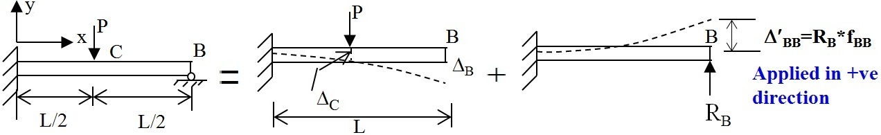
-
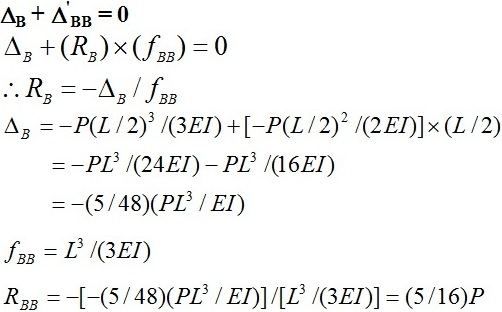
- The governing compatibility equation at B is
- By releasing the moment constraint at A, and making the structure a simply supported beam (which is once again, a determinate beam).
- The governing compatibility equation at B is

Overview of Method of Consistent Deformation
To recapitulate on what we have done earlier, Structure with single degree of indeterminacy:

(a) Remove the redundant to make the structure determinate (primary structure)

(b) Apply unit force on the structure, in the direction of the redundant, and find the displacement

Δ B0 + fBB x RB = 0
5. Indeterminate beam with Multiple Degrees of Indetermincay

(a) Make the structure determinate (by releasing the supports at B, C and D) and determine the deflections at B, C and D in the direction of removed redundant, viz.,Δ BO, Δ CO and Δ DO

(b) Apply unit loads at B, C and D, in a sequential manner and determine deformations at B, C and D, respectively.
(c ) Establish compatibility conditions at B, C and D
Δ BO + fBBRB + fBCRC + fBDRD = 0
Δ CO + fCBRB + fCCRC + fCDRD = 0
Δ DO + fDBRB + fDCRC + fDDRD = 0

Compatibility conditions at B, C and D give the following equations:
Δ BO + fBBRB + fBCRC + fBDRD = Δ B
Δ CO + fCBRB + fCCRC + fCDRD = Δ C
Δ DO + fDBRB + fDCRC + fDDRD = Δ D
6. Truss Structures

(a) Remove the redundant member (say AB) and make the structure a primary determinate structure
The condition for stability and indeterminacy is:
r + m > = < 2j
Since, m = 6, r = 3, j = 4, (r + m =) 3 + 6 > (2j =) 2 x 4 or 9 > 8 Δ i = 1
(b) Find deformation Δ ABO along AB:
Δ ABO =Δ (F0uABL)/AE
F0 = Force in member of the primary structure due to applied load
uAB= Forces in members due to unit force applied along AB
(c) Determine deformation along AB due to unit load applied along AB:

(d) Apply compatibility condition along AB:
ΔABO+fAB,ABFAB=0
Hence determine FAB
(e) Determine the individual member forces in a particular member CE by
FCE = FCE0 + uCE FAB
where FCE0 = force in CE due to applied loads on primary structure (=F0), and uCE = force in CE due to unit force applied along AB (= uAB)
7. Temperature changes affect the internal forces in a structure
Similarly fabrication errors also affect the internal forces in a structure
(i) Subject the primary structure to temperature changes and fabrication errors. - Find the deformations in the redundant direction
Reintroduce the removed members back and make the deformation compatible