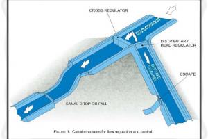
Design of Water Channel (Canals)

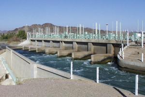
The channel is the same thing that is used for the water carriage purpose, however in case of hydropower projects the channel that takes water from the intake (Diversion Structure) is usually called connecting channel. It's tunnel is to be used in between the intake and power house otherwise called headrace channel, if no tunnel is to be used in between the intake and power house.
Lets take a general Example of design of small channel with design discharge of 390 lit/sec.
Design of Canal / Channel Design
Design discharge of the channel Q = 390 lps
Length of the channel L = 65 m
Cross sectional area of the channel A = Q / V = 0.39 / 1.0
= 0.39 m2
V = max. velocity permissible through the channel = 1.0 m/s
Cross sectional dimensions of the Water channel
From economic consideration
Top width = T = 2d
Area A = T x d = 2d2
Depth d =0.39/2 = 0.44 m
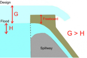
Provide a free board of 15cm
Total depth D = 0.60 m
Base width B = 0.44 x 2 = 0.88 m ~ 0.9 m
Hydraulic radius R = wetted area = A/P = 0.90 x 0.45
wetted perimeter 0.90 + 0.45 x 2 = 0.225
Channel bed slope S = nv 2 R 2/3 = 0.015 x 1.0 2 = 0.00164(0.225) 2/3
Head loss = Channel bed slope x Length of the channel = 0.00164x 65 = 0.11m