To Determine Yield & Tensile Strength of a Steel Bar

Apparatus:
UTM, Test Specimen, Vernier Calipers, Ruler etc.
Description of UTM:
A machine designed to perform tensile, compression, bend and shear tests, is called UTM,. It mainly consists of two parts.
- Loading Unit, control unit. In addition to these units, there are certain accessories like bending table, jaws for gripping recorders etc.
- Loading unit consists of two crossheads i.e upper cross head and lower cross head and a table
Procedure:
-
Prepare a test specimen of at least two feet.
-
Measure caliper at least at three places and then find average.
-
Insert the suitable jaws in the grip and select a suitable load scale on UTM.
-
Insert the specimen in the grip by adjusting the cross heads of UTM.
-
Start machine and continue applying the load.
-
At a point when the values of the load at that point this is called yield point.
-
When the specimen breaks stop the machine.
-
Note the ultimate value of the load.
-
Determine the yield strength and tensile strength of load dividing the yield load & ultimate load by cross sectional area of the bar.
Gauge length = 8 inch
Determine the yield strength by the following methods:
Offset Method
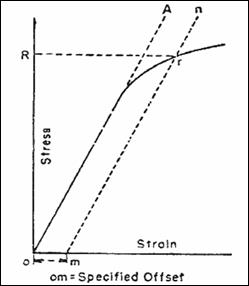 To determine the yield strength by the this method, it is necessary to secure data (autographic or numerical) from which a stress-strain diagram with a distinct modulus characteristic of the material being tested may be drawn. Then on the stress-strain diagram, lay off om equal to the specified value of the offset (i.e. yield strength ~0.2%), draw mn parallel to OA, and thus locate r, the intersection of mn with the stress-strain curve corresponding to load R, which is the yield strength load. In recording values of yield strength obtained by this method, the value of offset specified or used, or both, shall be stated in parentheses after the term yield strength.
Figure - Stress-strain diagram for the determination of yield strength by the offset method.
Secant Method
This method is also referred as the tangent, secant or chord modulus for the line drawn from the shear stress-shear strain curve at 5% (1/20) and 33% (1/3) of the maximum compressive shear stress. This region usually lies well within reasonably linear part of the curve. Lower part of the curve, representing a straight region being associated with closing up the interfaces between mortar and units is ignored, as they normally close up due to self weight in real structures. Calculations for Ec are as follows.
Ec = ∆ Shear Stress / ∆Shear Strain
∆ Shear Stress = (Shear stress corresponding to 1/3 of the compressive strength) - (Shear stress corresponding to 1/20 of the compressive strength)
∆ Shear Strain = Difference of the Shear strain at corresponding values of Shear stress.
ASTM Standards
|
Strength |
Grade 40 |
Grade 60 |
Grade 75 |
|
Minimum Yield Strength |
40,000 Psi |
60,000 Psi |
75,000 Psi |
|
Maximum Yield Strength |
60,000 Psi |
90,000 Psi |
1,00,000 Psi |
Elongation = 9.8 – 8 = 1.9
|
S No |
Dia of Bar |
Yield Load(Tons) |
Ultimate load(Tons) |
Area of Bar, |
Yield Strength=Yield Load *2204/ Area |
Tensile Strength = Yield Load*2204/ Area |
|
1 |
½ in |
5.97 |
9.28 |
0.196 in2 |
67132.04 Psi |
104352. 65 Psi |
|
2 |
½ in |
4.86 |
7.65 |
0.196 in2 |
54650.20 Psi |
86023. 46 Psi |
|
3 |
½ in |
5.47 |
8.11 |
0.196 in2 |
61509.62 Psi |
91196. 12 Psi |
|
4 |
½ in |
5.43 |
8.313 |
0.196 in2 |
61059.85 Psi |
93445. 10 Psi |
|
5 |
1/8 in |
7.05 |
10.95 |
0.306 in2 |
50778.43 Psi |
78868. 62 Psi |