List of Drawings Required for Building Construction

Drawings Required for Building Construction
For any construction project (in this case buildings), construction documents, drawings, sketches and plans are needed for proper execution of the project. There can be plenty of different documents that make up your set. Different clients and buildings have different requirements. Even the scope of the budget for the project can change the drawing requirements of the project. However, certain conventions have become widely accepted. Following are the types of Drawings in a Typical Set of Construction Documents:
- Architectural Drawings
- Electrical Drawings
- Plumbing Drawings
- Structural Drawings
- Fire Fighting Drawings
- HVAC Drawings
- Landscape and Site Drawings
1. Architectural Drawings
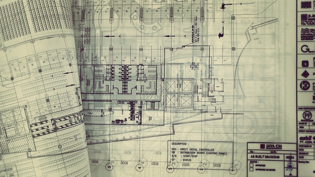
An architectural drawing is a technical drawing of a building (or building project) that is used by architects to develop a design idea into a coherent proposal, to communicate ideas and concepts, to convince clients of the merits of a design, to enable a building contractor to construct it, as a record of the completed work, and to make a record of a building that already exists. These drawings provide an overall view of the building's design and layout. They include floor plans, elevations, sections, and details that show the dimensions, arrangement, and appearance of the building. Architectural drawings also indicate the location of walls, doors, windows, stairs, and other architectural features.
The following are typical components found in a full set of  Architectural Construction Drawings:
- Setting Out Plan
- Floor Plans
- Elevation Drawings
- Section Drawings
- Working Drawings
- Opening Schedules
- Rood Drainage Plan
- Flooring Plan
- Furniture Plan
- Typical Details
2. Electrification Drawings
These drawings illustrate the electrical systems of the building, including the location of electrical panels, outlets, switches, lighting fixtures, and other electrical components. They provide information on circuit layouts, wiring diagrams, and electrical load calculations. These drawings shows the location of electrical equipment and their layout in the building.
- Electrical Legend
- Floor Lighting Plan
- Floor Power Plan
- Single Line Diagram
- Fire Alarm Layout
- Floor Sound System and CCTV Camera
- Equivalency Chart
- Lightening Protection Earthing Details
3. Public Health Drawings
Plumbing and Sanitary drawings show the plumbing and sanitary systems of the building, including water supply lines, drainage pipes, fixtures, and equipment. They indicate the layout, sizes, and connections of plumbing and sanitary fixtures, such as sinks, toilets, showers, and drainage points.
- Legend and General Notes
- Sewerage and Rainwater Layout Plan
- Manhole Schedule
- Plumbing Construction Details
- Water Supply Layout
4. Structural Drawings
These drawings depict the structural elements of the building, including foundations, columns, beams, slabs, and other load-bearing components. They provide information about the structural design, sizes, reinforcements, and connections. Structural drawings are critical for ensuring the structural integrity and safety of the building. These drawings show the support system of the building like how the building is standing, what are its structural components, what is the strength of the building and how beams, columns, stairs, slabs etc. are connected and thus like.
- General Notes
- Typical sections
- Foundation excavation plan
- Footing sections
- Ground floor column plan
- Column sections
- Ground floor plinth beams plan
- Plinth beams sections
- Ground floor beam plan
- Beam sections
- Ground floor slab bottom rebar detail
- Ground floor slab top rebar detail
- Ground floor slab section
- Overhead water tank design
- Septic tank design
5. Fire Fighting Drawings
These drawings outline the fire protection systems of the building, including fire sprinklers, fire alarms, smoke detectors, fire extinguishers, and emergency exits. They indicate the locations, types, and installation details of these fire safety features.
- Legend and Notes
- Fire Fighting Layout Plan (For Each Floor)
6. HVAC Drawings
- Legend and General Notes
- AC Layout Plan (for each Floor)
- Equipment Schedule and Installation Detail
7. Landscape and Site Drawings:
These drawings focus on the site layout, landscape design, and site improvements. They include information on grading, drainage, planting, hardscape elements, parking areas, and other site-specific features.