Khosla's Theory of Hydraulic Structures

After studying a lot of dam failure constructed based on Bligh’s theory, Khosla came out with his own findings. Following are some of the main points from Khosla's Theory
From observation of Siphons designed on Bligh's theory, by actual measurement of pressure, with the help of pipes inserted in the floor of two of the siphons does not show any relationship with pressure calculated on Bligh's theory. This led to the following provisional conclusions:
- Outer faces of end sheet piles were much more effective than the inner ones and the horizontal length of the floor.
- Intermediated piles of smaller length were ineffective except for local redistribution of pressure.
- Undermining of floor started from tail end.
- It was absolutely essential to have a reasonably deep vertical cut off at the downstream end to prevent undermining.
- Khosla and his associates took into account the flow pattern below the impermeable base of hydraulic structure to calculate uplift pressure and exit gradient.
- Starting with a simple case of horizontal flow with negligibly small thickness. (various cases were analyzed mathematically.)
- Seeping water below a hydraulic structure does not follow the bottom profile of the impervious floor as stated by Bligh but each particle traces its path along a series of streamlines.
For case of two dimensional flows under a straight floor where:
Thus for the first flow line AB which touches the outline of the floor, the pressure can be obtained by putting different values of x in equation. Fig shows the pressure distribution diameter both by equation 4 as well as Bligh's Theory. From the fig the following conclusions can be drawn:
Slope of Pressure diagram: At A and B in infinite, hence the floor at A will be theoretically infinite acting downward and that at B will also be infinite acting upward. This will cause sand boiling and hence the floor should be depressed or cut off should be provided at the downstream end.
Composite profile:
The following specific causes of general form were considered in Khosla's Theory
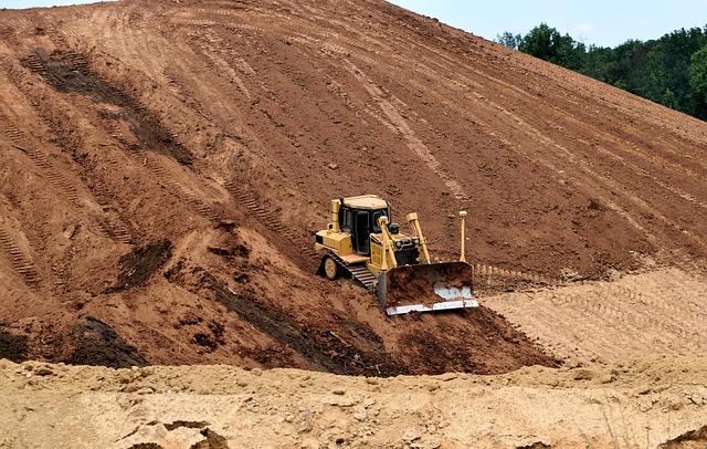
- Straight horizontal flow of negligible thickness with pile at either end, upstream or at downstream end.
- Straight horizontal floor of negligible thickness with pile at some intermediate point.
- Straight horizontal floor, depressed below the bed, but with no cut off.
Method of independent variable:
- Most designs do not confirm to elementary profiles (specific cases). In actual cases we may have a number of piles at upstream level, downstream level and intermediate points and the floor also has some thickness.
- Khosla solved the actual problem by an empirical method known as method of independent variables.
- This method consists of breaking up a complex profile into a number of simple profiles, each of which is independently amiable to mathematical treatment. Then apply corrections due to thickness of slope of floor.
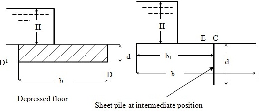
- As an example the complex profile shown in fig is broken up to the following simple profile and the pressure at Key Points obtained.
- Straight floor of negligible thickness with pile at upstream ends.
- Straight floor of negligible thickness with pile at downstream end.
- Straight floor of negligible thickness with pile at intermediate points.
- The pressure is obtained at the key points by considering the simple profile.
For the determination of seepage below the foundation of hydraulic structure developed the method of independent variable.
In this method, the actual profile of a weir which is complex, is divided into a number simple profiles, each of which cab be solved mathematically without much difficulty. The most useful profile considered are:
A straight horizontal floor of negligible thickness provided with a sheet pile at the upstream end or a sheet pile at the downstream end.
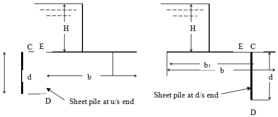
ii) A straight horizontal floor depressed below the bed, but without any vertical cut-off.
- A straight horizontal floor of negligible thickness with a sheet pile at some
Intermediate point
The mathematical solution of the flow-nets of the above profiles have been given in the form of curves. From the curves, percentage pressures at various key points E, C, E1, C1 etc) be determined. The important points to note are:
- Junctions of pile with the floor on either side{E, C (bottom), E1, C1 (top) }
- Bottom point of the pile (D), and
- Junction of the bottom corners (D, D’) in case of depressed floor
The percentage pressures at the key points of a simple forms will become valid for any complex profile, provided the following corrections are effected:
- correction for mutual interference of piles
- correction for the thickness of floor
- correction for slope of the floor
Corrections for Khosla Theory Explained
Correction for Mutual Interference of Piles
Let b1 = distance between the two piles 1 and 2, and
D = the depth of the pile line (2), the influence of which on the neighboring pile (1) of depth d must be determined
b = total length of the impervious floor
c = correction due to interference.
The correction is applied as a percentage of the head

This correction is positive when the point is considered to be at the rear of the interfering pile and negative for points considered in the forward or flow direction with the interfering pile.
Correction for Floor Thickness
Standard profiles assuming the floors as having negligible thickness. Hence the values of the percentage pressures computed from the curves corresponds to the top levels (E1*, C1*) of the floor. However, the junction points of the floor and pile are at the bottom of the floor (E1, C1)
The pressures at the actual points E1 and C1 are interpolated by assuming a straight line variation in pressures from the points E1* to D1 and from D1 to C1
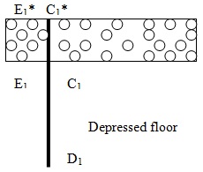
The corrected pressures at E1 should be less than the computed pressure t E1*. Therefore the correction for the pressure at E1 will be negative. And so also is for pressure at C1.
Correction for Slope of Floor
A correction for a sloping impervious floor is positive for the down slope in the flow direction and negative for the up slope in the direction of flow.
|
No. |
Slope = Ver:Horiz |
Correction as % of pressure |
|
1 |
1:1 |
11.2 |
|
2 |
1:2 |
6.5 |
|
3 |
1:3 |
4.5 |
|
4 |
1:4 |
3.3 |
|
5 |
1:5 |
2.8 |
|
6 |
1:6 |
2.5 |
|
7 |
1:7 |
2.3 |
|
8 |
1:8 |
2.0 |
The correction factor must be multiplied by the horizontal length of the slope and divided by the distance between the two poles between which the sloping floor exists. In the diagram above, correction for slope can be applied only to point E2. As the point E2 is terminating at the descending slope in the direction of flow, the correction will be positive. The value of correction will be:
C.F. x bs/b1
Where C.F. =correction factor
bs = horizontal length of sloping floor
b1 = horizontal distance between the pile lines
Exit & Critical Gradient
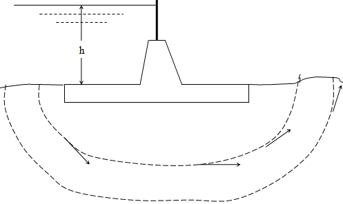
Every particle of water while seeping through the sub-soil, at any position will exert a force f, which will be tangential to the streamline at any point. As the streamlines bend upward, the tangential force f will be having a vertical component f1. Also at that point, there will be a downward force W due to the submerged weight of the soil particle. Thus at that point there will be two forces on the particle; one upward vertical component of f, and the other, the submerged weight. It is evident that if the soil particle is not to be dislodged, then the submerged weight must be greater than the upward vertical component of f. The upward vertical component force at any point is proportional to the water pressure gradient dp/dx.
Hence for stability of the soil and for the prevention of erosion and piping, the seeping water when it emerges at the downstream side, at the exit position, the force f1 should be less than the submerged weight W. In other words the exit gradient at the downstream end must be safe.
If at the exit point at the downstream side, the exit gradient is such that the force f1is just equal to the submerged weight of the soil particle, then that gradient is called critical gradient. Safe exit gradients = 0.2 to 0.25 of the critical exit gradient.
Values of safe exit gradient may be taken as:
- 0.14 to 0.17 for fine sand
- 0.17 to 0.20 for coarse sand
- 0.20 to 0.25 for shingle
For the standard form consisting of a floor of a length b, and a vertical cut-off of depth d, the exit gradient at its downstream end is given by:
Exit gradient GE = (H/d) x ![]()